Build Your Own Continuous Integration Pole
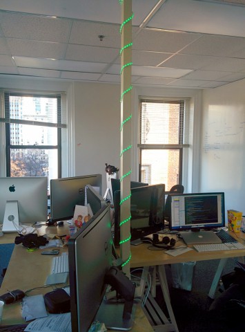
If you live in Boston and happen to walk around the Commons when evening falls, you may have noticed a strange glow coming from the top of one the building along the park:

This eerie light comes from our designer pole, an experiment I did to provide cheap feedback over our build status in our continuous integration system:
The setup is based around 3 main components: a Raspberry Pi, a 5V relay module board and a basic 12V RGB LED strip. You can buy all those parts directly from Amazon for about $112 total (of which $77 was for a premium Raspberry Pi package but it’s up to you).
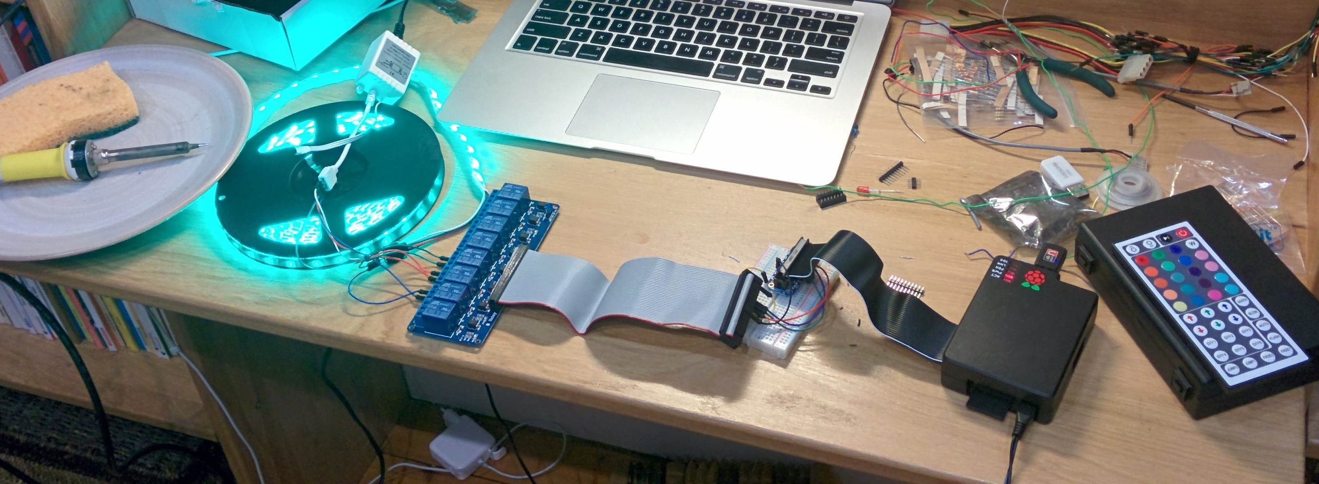
No matter the RGB LED strip “brand” you end up buying (it all seems to be from the same generic supplier), the wiring is pretty simple and consist of a common ground and a wire for each color channel (red, green, blue) so 4 wires in total.
Thus in the simplest form we can very easily turn on and off those channels using a bunch of relays. Each build status (success, test failure and build failure) will be mapped to a specific color (green, blue, red respectively).
A relay is the basic building block to control a power circuit (the 12V DC from the LED strip power adapter) from a control circuit (the 3.3V DC of the Raspberry Pi). There are a bunch of different designs available (magnetic, solid state, …) depending on the amount of power you are controlling. For this type of setup pretty much anything should work (it’s just LEDs after all).
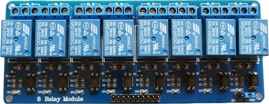
Those relays are then mounted on a board like the one in the picture to conveniently expose a control interface that you can plug to your Raspberry Pi GPIO ports. That’s the final product you can buy (unless you want to do your own PCB).
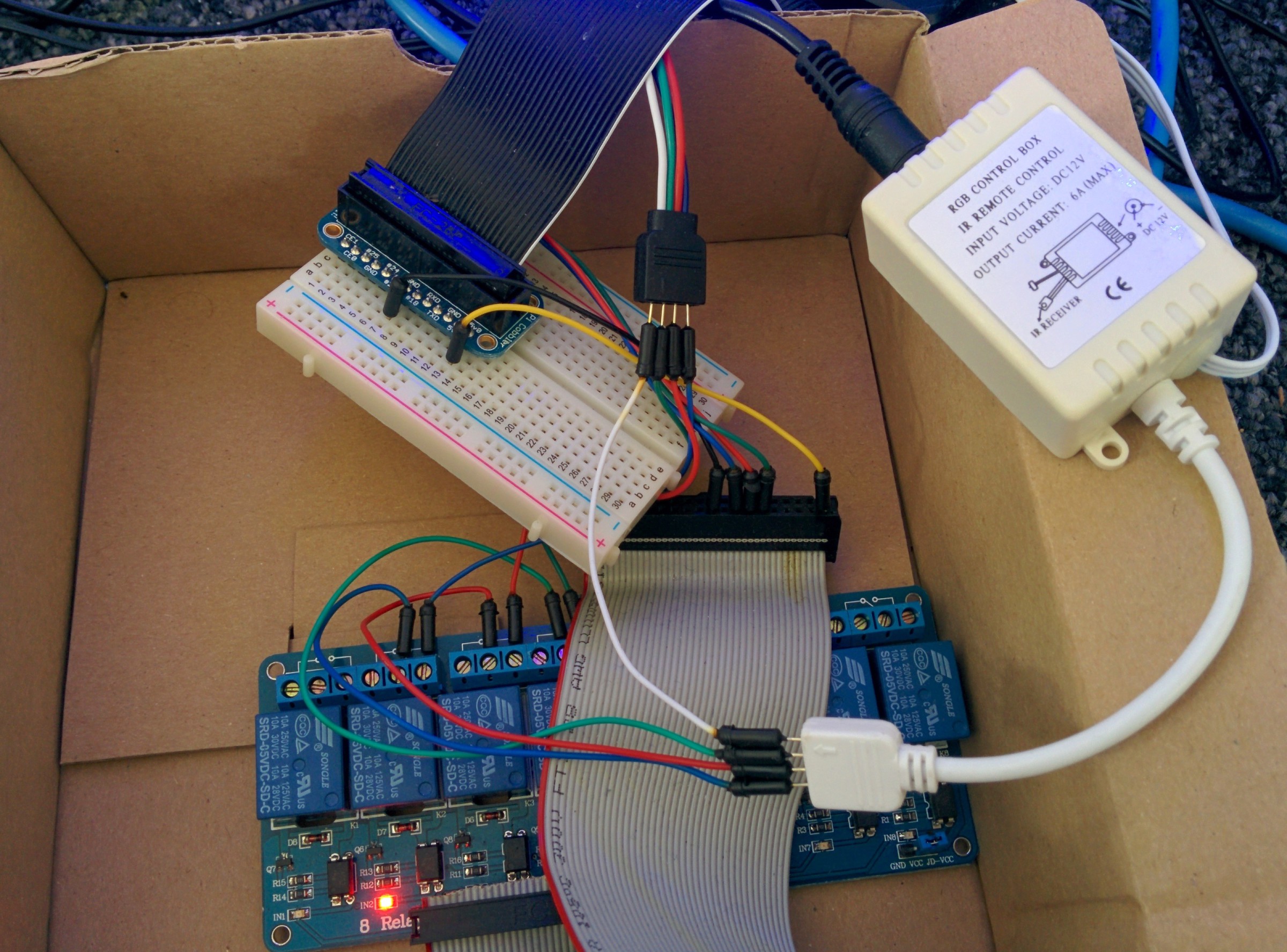
Below is a close-up of the wiring between all the different pieces, the GPIO ports are exported to the breadboard and then connected onto the relay module control circuit.
I also made a more schematic version so that you can see which GPIO ports are used:
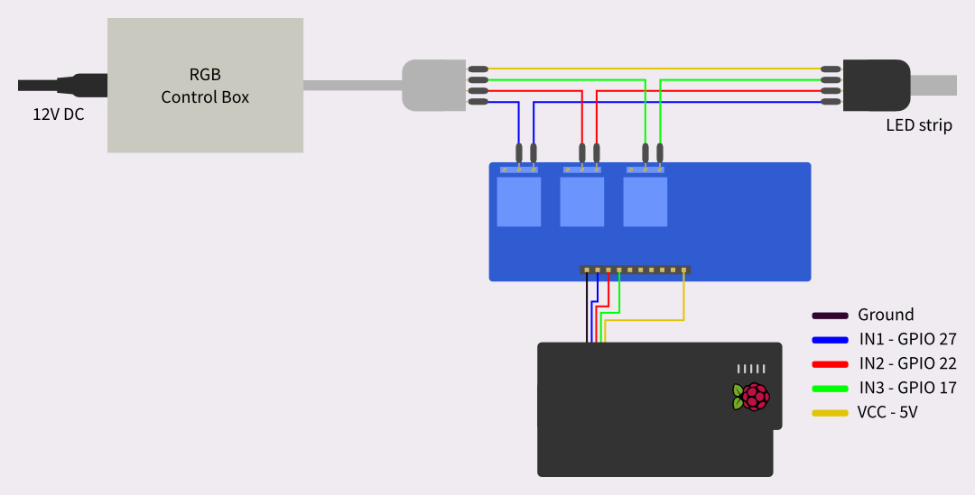
The common of the LED strip (the white cable) is connected directly to the power source (we don’t care about controlling it). All the other color wires go in and out of their own relay.
If you are short on connectors, you may have noticed a little trick I use which is to go scavenge your old computers for IDE connectors (what you used to plug your old harddrive, floppy disk readers and the likes). They fit perfectly well and have the same type of wire that standard Dupont cables.
Below is the part of the code that controls the relay module to turn on and off the LEDs:
using System;
using System.Threading;
using RaspberryPiDotNet;

namespace WrenchBerry
{
	public static class Ledder
	{
		public enum Color {
			Green,
			Orange,
			Red
		}

		static GPIOPins[] pinMapping = new GPIOPins[] {
			GPIOPins.V2_GPIO_17,
			GPIOPins.V2_GPIO_27,
			GPIOPins.V2_GPIO_22,
		};

		public static void FlashLed (Color color, int times = 3)
		{
			var pin = pinMapping [(int)color];
			for (int i = 0; i < times; i++) {
				GPIO.Write (pin, true);
				Thread.Sleep (500);
				GPIO.Write (pin, false);
				Thread.Sleep (500);
			}
		}

		public static void TurnOn (Color color)
		{
			var pin = pinMapping [(int)color];
			GPIO.Write (pin, false);
		}

		public static void TurnAllColorOff ()
		{
			foreach (var pin in pinMapping)
				GPIO.Write (pin, true);
		}
	}
}
The code use the RaspberryPi.Net library to directly access the chip memory controlling the GPIO pins.
The main program is then a super-simplistic infinite loop over the CI results:
using System;
using System.IO;
using System.Linq;

namespace WrenchBerry
{
	class MainClass
	{
		const Ledder.Color NoColor = (Ledder.Color)(-1);
		static Ledder.Color currentColor = NoColor;

		public static void Main (string[] args)
		{
			var lane = args [0];

			while (true) {
				try {
					var builds = CISystem.GetStateListFromLane (lane);
					if (builds == null || builds.Length == 0 || !builds.Any (IsFinishedState)) {
					    Console.WriteLine ("Lane or fetching is fucked up");
					    return;
					}
					var firstBuilt = builds.First (IsFinishedState);
					Console.WriteLine (DateTime.Now.ToString ("u") + " - " + firstBuilt);

					Ledder.Color color = GetColorForState (firstBuilt);

					if (color != NoColor && currentColor != color) {
					    Ledder.TurnAllColorOff ();
					    Ledder.FlashLed (color);
					    Ledder.TurnOn (color);
					}
					currentColor = color;
				} catch (Exception e) {
					Console.WriteLine (e);
				}

				System.Threading.Thread.Sleep ((int)TimeSpan.FromMinutes (2).TotalMilliseconds);
			}
		}

		static Ledder.Color GetColorForState (DBState state)
		{
			Ledder.Color color = NoColor;
			switch (state) {
			case DBState.Failed:
				color = Ledder.Color.Red;
				break;
			case DBState.Issues:
				color = Ledder.Color.Orange;
				break;
			case DBState.Success:
				color = Ledder.Color.Green;
				break;
			}
			return color;
		}

		static bool IsFinishedState (DBState state)
		{
			return state == DBState.Failed || state == DBState.Issues || state == DBState.Success;
		}
	}
}
All that’s left to do is to make yourself a nice little storage area and, why not, spice up the system a little bit. For instance in our setup (pictured below) I also hooked up a small speaker.
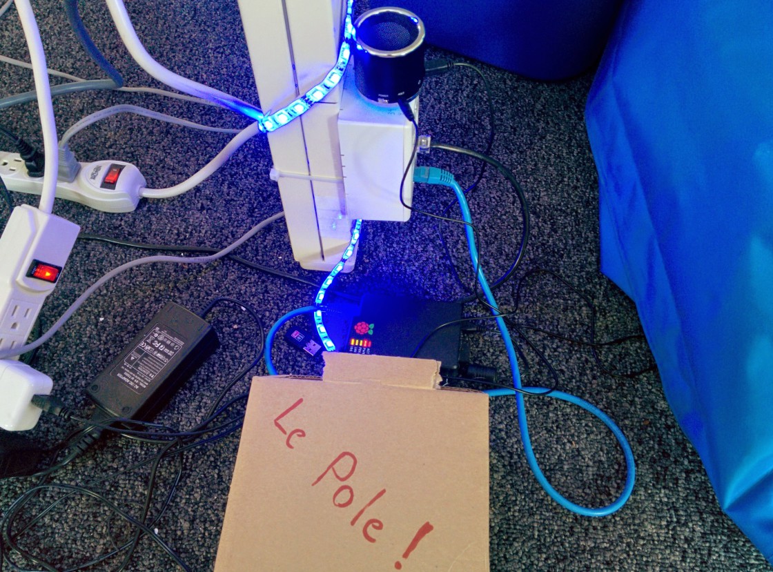
As an example our current playlist consist of: the Imperial March (build failure), Mass Effect Reaper sound (test failure) and, last but not least, our friend He-Man (build success).
Happy (hardware) hacking!